Cisco vPC aka Virtual Port-Channel, which was launched in 2009 is a feature on the Cisco Nexus series switches that allows end device to configure a Port-Channel across multiple switches. If you want to know details, then check fundamental concepts of vPC by Cisco. In this lesson, we will learn how to configure Cisco Nexus vPC. We will do this in following steps-
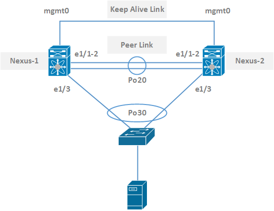
Topology:
Configuration:
Enabling Features:
First of all, let’s enable necessary features for vPC on both switches.
Nexus-1:
Nexus-1(config)# feature vpc
Nexus-1(config)# feature lacp

Nexus-2:
Nexus-2(config)# feature vpc
Nexus-2(config)# feature lacp
Keep Alive Link:
For keep alive link, we will use our management interfaces. However, for a larger enterprise network, management interfaces are used for out-of-band management. In that case, you will need to use other ports.
Nexus-1:
Nexus-1(config)# interface mgmt 0
Nexus-1(config-if)# ip address 10.1.1.1/30
Nexus-1(config-if)# no shutdown

Nexus-2:
Nexus-2(config)# interface mgmt 0
Nexus-2(config-if)# ip address 10.1.1.2/30
Nexus-2(config-if)# no shutdown
To verify the connectivity, we can ping from Nexus-1 to Nexus-2 management IP.
Nexus-1# ping 10.1.1.2 vrf management
PING 10.1.1.2 (10.1.1.2): 56 data bytes
36 bytes from 1.1.1.1: Destination Host Unreachable Request 0 timed out
64 bytes from 10.1.1.2: icmp_seq=1 ttl=254 time=1.098 ms
64 bytes from 10.1.1.2: icmp_seq=2 ttl=254 time=0.598 ms
64 bytes from 10.1.1.2: icmp_seq=3 ttl=254 time=0.536 ms
64 bytes from 10.1.1.2: icmp_seq=4 ttl=254 time=0.503 ms

--- 10.1.1.2 ping statistics ---
5 packets transmitted, 4 packets received, 20.00% packet loss
round-trip min/avg/max = 0.503/0.683/1.098 ms
vPC Domain:
A vPC domain is a collection of vPC component. In this example, we will be using vPC domain 1. You can choose domain id between <1-1000>. And, also we will set priorities for both switches. Lower priority will become primary.
Nexus-1:
Nexus-1(config)# vpc domain 1
Nexus-1(config-vpc-domain)# role priority 20
Nexus-1(config-vpc-domain)# peer-keepalive destination 10.1.1.2 source 10.1.1.1 vrf management
Nexus-1(config-vpc-domain)#

Nexus-2:
Nexus-2(config)# vpc domain 1
Nexus-1(config-vpc-domain)# role priority 30
Nexus-2(config-vpc-domain)# peer-keepalive destination 10.1.1.1 source 10.1.1.2 vrf management
Nexus-2(config-vpc-domain)#
Peer Link:
The peer link exchanges state information and carries control traffic between peer nexus switches.
Nexus-1:
Nexus-1(config)# interface ethernet 1/1-2
Nexus-1(config-if-range)# channel-group 20 mode active
Nexus-1(config-if-range)# no shutdown

Nexus-1(config)# interface port-channel 20
Nexus-1(config-if)# no shutdown
Nexus-1(config-if)# switchport
Nexus-1(config-if)# switchport mode trunk
Nexus-1(config-if)# vpc peer-link

Nexus-2:
Nexus-2(config)# interface ethernet 1/1-2
Nexus-2(config-if-range)# channel-group 20 mode active
Nexus-1(config-if-range)# no shutdown

Nexus-2(config)# interface port-channel 20
Nexus-2(config-if)# no shut
Nexus-2(config-if)# switchport
Nexus-2(config-if)# switchport mode trunk
Nexus-2(config-if)# vpc peer-link
To verify, use need to use, “show vpc brief” command.
Nexus-1# show vpc brief
Legend:
                (*) - local vPC is down, forwarding via vPC peer-link

vPC domain id                     	: 1
Peer status                       		: peer adjacency formed ok
vPC keep-alive status             	: peer is alive
Configuration consistency status  : success
Per-vlan consistency status       	: success
Type-2 consistency status         	: success
vPC role                          		: primary
Number of vPCs configured         : 0
Peer Gateway                      	: Disabled
Dual-active excluded VLANs        : -
Graceful Consistency Check        : Enabled
Auto-recovery status              	: Disabled
Delay-restore status              	: Timer is off.(timeout = 30s)
Delay-restore SVI status          	: Timer is off.(timeout = 10s)
Operational Layer3 Peer-router    : Disabled

vPC Peer-link status
---------------------------------------------------------------------
id    Port   Status Active vlans
--    ----   ------ -------------------------------------------------
1     Po20   up     1
Member Ports:
Member ports are the ports where end device is connected. We need to configure port-channel for the end device.
Nexus-1:
Nexus-1(config)# interface eth 1/3
Nexus-1(config-if)# channel-group 30 mode active
!
Nexus-1(config-if)# interface port-channel 30
Nexus-1(config-if)# switchport
Nexus-1(config-if)# switchport mode access
Nexus-1(config-if)# switchport access vlan 30
Nexus-1(config-if)# vpc 30

Nexus-2:
Nexus-2(config)# interface eth 1/3
Nexus-2(config-if)# channel-group 30 mode active
!
Nexus-2(config-if)# interface port-channel 30
Nexus-2(config-if)# switchport
Nexus-2(config-if)# switchport mode access
Nexus-2(config-if)# switchport access vlan 30
Nexus-2(config-if)# vpc 30
Let’s verify VPC member.
Nexus-1# show vpc brief
Legend:
                (*) - local vPC is down, forwarding via vPC peer-link

vPC domain id                     	: 1
Peer status                       		: peer adjacency formed ok
vPC keep-alive status             	: peer is alive
Configuration consistency status  : success
Per-vlan consistency status       	: success
Type-2 consistency status         	: success
vPC role                          		: primary
Number of vPCs configured         : 1
Peer Gateway                      	: Disabled
Dual-active excluded VLANs        : -
Graceful Consistency Check        : Enabled
Auto-recovery status              	: Disabled
Delay-restore status              	: Timer is off.(timeout = 30s)
Delay-restore SVI status          	: Timer is off.(timeout = 10s)
Operational Layer3 Peer-router    : Disabled

vPC Peer-link status
---------------------------------------------------------------------
id    Port   Status Active vlans
--    ----   ------ -------------------------------------------------
1     Po20   up     1

vPC status
----------------------------------------------------------------------------
Id    Port          Status Consistency Reason                Active vlans
--    ------------  ------ ----------- ------                ---------------
30    Po30          down*  success     success               30
Member port Po30 is added. It’s showing down, because the end device (port-channel) still not configured. You need to create a port-channel in below switch.
Orphan Ports:
Orphan Ports is the port, which are not under any VPC member ports. You can verify it by using “show vpc orphan-ports”.
I’d like to know what the configuration would be if the N9Ks came directly to the server?
Would there still be Po30s?
If server can connect with both swtiches, then no issue.
Hey,
what will happen if there are several vlan, will they all be able to go through Po30?
Yes, they will.
Hello Sir,
I have three nexus 9k switches for redundancy. I dont have enough ports on my primary and sec nexus switches, so i want to conbine them as one switch, so i connect all my primary server links on them and the backup links on the third or the access switch. is it possible and what problems this design will face. Thank you
So your plan is to stack two switches and designate them as the primary switch for the VPC, with the third switch as the secondary VPC node. Technically, I can’t see any problem here, but it’s not a common design.
Hello Sir,
When we use multiple VRFs and configure multiple VLANs inside the VRF, how do we configure VPC?
It should be simple. Are you facing any challenges?
Were do u add the IP Gateway address for each VLAN (interval routing)
You can configure your gateway anywhere like switch/firewall/router.
Hi Sir,
N3K-C3524P-10GX VPC configuration to use VRF command which LAN enterprise license is required or not. Please kindly suggest to me.
vPC feature is included in the base NX-OS software license. Additional licenses is not required.
Hii, Pls say..
How do I run RSTP over VPC? Do I set same or separate RSTP priority value like 0 or 4064 to both NX-SW to make VPC domain root bridge for VPC member or orphan ports?
Need to use same priority for both nodes.
You are doing a great job with these articles, they are descriptive & on point in a way without giving a feel like we are missing the key details.
Keep up the good work sir!
Hi Mohit, thanks for your nice comment.
Hi Rajib,
Thanks for sharing this info! I got a question, can we have redundant “Peer-Keepalive”? I currently use mgmt0 as Peer-Keepalive. What if the mgmt0 port or cable fails? Can we have a redundant L3 SVI or L3 Port-Channel as backup “Peer-Keepalive”?
Do we use the same “management” VRF for the redundant “Peer-Keepalive” or use a separate VRF (i.e. management2)?
interface mgmt0
vrf member management
ip address 192.168.1.1/24
vlan 99
interface vlan 99
vrf member management2
ip address 10.1.1.1/24
vpc domain 1
role priority 10
peer-keepalive destination 192.168.1.2 source 192.168.1.1 vrf management
peer-keepalive destination 10.1.1.2 source 10.1.1.1 vrf management2 <<<
You can’t use two separate keep-alive links. However, there is an easy way to do that.
Create a port channel with multiple links and then declare that port-channel as keep-alive. Easy 🙂
Hey Rajib ,
how about using an SVI for keep-alive ( if there are not l3 modules), can you write an optional configuration for the same.
SVI will work. However, it’s not recommended.
BTW, now all M and F series support L3.
Is it possible to pass vrf keepalive peers in peer link. my DC and DR are located in different locations with LACP. I want this LACP as peer links and use keepalive vrf in this. It’s no possible to use another or dedicated port for keepalive vrf link.
Hi Faizullah, your requirement is not clear. Why you need Peer-link and Keep-alive link between datacenters?
If you requirement is DCI using VPC, then Peer-link and Keep-alive link will be within datacenter not between datacenters.
Hello Sir,
One question please, instead using management port for keep-alive vrf, or a other ethernet physical port (I don’t want to use 10G port just for keep-alive).
Can I use an existing vlan ports or loopback interfaces? knowing that they are layer 3 reachable. If yes, how the configuration will be?
Thank you Sir
Hi Mostafa, yes you can. But, keep-alive is very important link. It’s deserve a dedicate connection.
You can read https://www.letsconfig.com/vpc-failure-scenarios-impact-and-solution/ to know what will happen if keep-alive is down.
Hello
We currently have the management ports connected to a switch stack. we use these for vpc keep alive. i would like connect these 2 ports together instead of going through a switch stack. Will there be any interruption when i unplug these ports and connect the 2 management ports together with a small patch cable?
“If only keep-alive fails, nothing will happen. Only heartbeat between Primary and Secondary node will be lost.” – https://www.letsconfig.com/vpc-failure-scenarios-impact-and-solution/
That means, you can do this without any interruption.
Hi Rajib, Thanks for this explanation in simplest way.
I have a question on below scenario.
Incase a server connected to nexus (N9K) switches (switches are in vpc-peer) having teaming at server side but no port channel and vpc configuration on nexus switches interfaces for this server, will it cause any traffic disruption if either of nexus switch fails ? as since this server connectivity is not in port channel or VPC at nexus side.
Hi Rajesh, you will face loop in your topology. There will be any service disruption or not, it will depends on the VPC design, Spanning-tree configuration and other few factors.
So i think, it’s easier and best for you to go with VPC for your server.
Hi, thank you for this explanation
in case of vPC Fabric Peering
peer-keepalive destination ” ” source ” ”
virtual peer-link destination ” ” source ” ” dscp 56
what should be the Src and Dst ? is the LO of VTEP primary IP in both switches or what ??
Hi Borair, you can watch ciscolive BRKDCN-2249 for better understanding on vpc with fabric peering.
Hi
Great post
Although I read that It is not recommended to carry non-vPC VLANs on the vPC Peer-Link, because this configuration could cause severe traffic disruption for the non-vPC VLANs if the vPC Peer-Link fails.
Then it is necessary to create a vlan for vPC .
BEST REGARDS
Hi David, there are many recommendation and best practices for VPC design and configuration. I will publish a new article on this soon.
Keep it up Rajib, I found this very useful.
Thanks Khalid. I will try my best.
This was very helpful. Also, great site. Thanks so much.
Hi anotherinternetuser, thank you so much.
Hello Sir,
I have two questions:
– If we lose the keepalive link, Is there a disturbance?
– For example, if we create the port-channel 1. Can we use vpc 1? Are there no problems with the domain ID ?
Hi Ritin,
– If we lose the keepalive link, Is there a disturbance?
+++ If only keep-alive fails, nothing will happen. Only heartbeat between Primary and Secondary node will be lost.
Below content is recommended for you-
https://www.letsconfig.com/vpc-failure-scenarios-impact-and-solution/
– For example, if we create the port-channel 1. Can we use vpc 1? Are there no problems with the domain ID ?
+++ Yes, you can.
Hi good day
What would happen if we didn’t put “vpc 30”, would that portchannel see it as an orphan?
If it is VPC VLAN (vlan pass through peer-link) and connected only one peer switch, then YES.
Clear explanation, straight to the point! Thank you for sharing this.
Thank you 🙂
Hello sir so you have done the configuration on primary and secondary switch. So what about below catalyst switch we have do configuration in that also?? If yes what kind of configuration we have to do in catalyst switch. Please help me.
Hi Saqib, you need to create a port-channel in below switch. And, allow VLANs as per your requirements (trunk/access).
Thank you sir.
Hi Rajib
If we have multiple ports to server from nexus
Do the server need to be configured in lacp or .3ad?
Yes, you need to configure LACP in your server end.
Hi Rajib, thank you for explanation. I managed to configure my switches easily! Just one question: instead using management port for keep-alive vrf, I would like to use an ethernet port (i.e. eth 1/48). How this config changes?
Hi Simone, you will need to create a new VRF (recommended) for keep-alive. You can use below command as reference-
vrf context VPC-Keepalive
description ***VPC-Keepalive***
interface Eth1/48
description ***VPC Keepalive link***
vrf member VPC-Keepalive
ip address x.x.x.x/30
no shutdown
Other configuration will remain same.
I already created new vrf but when i tried to ping into another switch it said no route to host. How can i solve this?
Did you use VRF to initiate ping?
HI rajib,
Its a simple and great explanation.Thank you.
Hi Sachin, you are welcome 🙂