A VLAN (virtual LAN) is a logical sub-networks of workstation. This is needed for network admin to partition a single switch network into many. It improves security and traffic management. In this lesson we will learn how to configure VLAN on Cisco Catalyst switches.
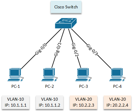
We will start with a simple network where we need to create and assign VLANs and segregate the networks between the workstation group.
Configuration:
Now, let’s check the default situation of vlan database by using “show vlan” command.
letsconfig-SW#show vlan

VLAN Name                             Status    Ports
---- -------------------------------- --------- -------------------------------
1    default                          active    Gi0/0, Gi0/1, Gi0/2, Gi0/3
                                                Gi1/0, Gi1/1, Gi1/2, Gi1/3
                                                Gi2/0, Gi2/1, Gi2/2, Gi2/3
                                                Gi3/0, Gi3/1, Gi3/2, Gi3/3
1002 fddi-default                     act/unsup
1003 token-ring-default               act/unsup
1004 fddinet-default                  act/unsup
1005 trnet-default                    act/unsup
Here we can see, VLAN 1 is assigned for all interfaces. Because of the same VLAN, we can communicate when a switch newly installed in a network. Important to point out here, you cannot delete vlan 1 using “no vlan 1” command, to remove vlan 1 you need to delete vlan database using “delete flash:vlan.dat” command.
However, now We will configure VLAN 10, 20 according our LAN topology diagram.
letsconfig-SW#conf t
letsconfig-SW(config)#vlan 10
letsconfig-SW(config-vlan)#name vlan-10
letsconfig-SW(config-vlan)#
letsconfig-SW(config-vlan)#vlan 20
letsconfig-SW(config-vlan)#name vlan-20
letsconfig-SW(config-vlan)#end
letsconfig-SW#
Let’s verify the output using “show vlan” command
letsconfig-SW#show vlan

VLAN Name                             Status    Ports
---- -------------------------------- --------- -------------------------------
1    default                          active    Gi0/0, Gi0/1, Gi0/2, Gi0/3
                                                Gi1/0, Gi1/1, Gi1/2, Gi1/3
                                                Gi2/0, Gi2/1, Gi2/2, Gi2/3
                                                Gi3/0, Gi3/1, Gi3/2, Gi3/3
10   vlan-10                          active
20   vlan-20                          active
1002 fddi-default                     act/unsup
1003 token-ring-default               act/unsup
1004 fddinet-default                  act/unsup
1005 trnet-default                    act/unsup
VLAN 10 and 20 are now in vlan database. However, no interfaces are assigned to them. Let’s configure vlan interfaces for our workstations.
letsconfig-SW#conf t
letsconfig-SW(config)#interface GigabitEthernet0/0
letsconfig-SW(config-if)#switchport mode access
letsconfig-SW(config-if)#switchport access vlan 10
letsconfig-SW(config-if)#^Z
letsconfig-SW#
We have assigned VLAN 10 on interface GigabitEthernet0/0.
Configuration for other interfaces are below –
letsconfig-SW(config)#int gigabitEthernet 0/1
letsconfig-SW(config-if)#switchport mode access
letsconfig-SW(config-if)#switchport access vlan 10
letsconfig-SW(config-if)#exit
letsconfig-SW(config)#
letsconfig-SW(config)#int gigabitEthernet 0/2
letsconfig-SW(config-if)#switchport mode access
letsconfig-SW(config-if)#switchport access vlan 20
letsconfig-SW(config-if)#exit
letsconfig-SW(config)#
letsconfig-SW(config)#int gigabitEthernet 0/3
letsconfig-SW(config-if)#switchport mode access
letsconfig-SW(config-if)#switchport access vlan 20
letsconfig-SW(config-if)#^Z
letsconfig-SW#
Here is our new output –
letsconfig-SW#show vlan

VLAN Name                             Status    Ports
---- -------------------------------- --------- -------------------------------
1    default                          active    Gi1/0, Gi1/1, Gi1/2, Gi1/3
                                                Gi2/0, Gi2/1, Gi2/2, Gi2/3
                                                Gi3/0, Gi3/1, Gi3/2, Gi3/3
10   vlan-10                          active    Gi0/0, Gi0/1
20   vlan-20                          active    Gi0/2, Gi0/3
1002 fddi-default                     act/unsup
1003 token-ring-default               act/unsup
1004 fddinet-default                  act/unsup
1005 trnet-default                    act/unsup
Interface Gi0/0, Gi0/1 is now under vlan 10 and Gi0/2, Gi0/3 is now under 20. So, according VLAN fundamental, PC-1 and PC-2 will not be able to communicate with PC-3 and PC-4 because they are on different VLAN, however, they will be communicating with each other (PC-1 to PC-2 and PC-3 to PC-4). Let’s test it by pinging.
(PC-1 to PC-2)
PC-1> ping 10.1.1.2
84 bytes from 10.1.1.2 icmp_seq=1 ttl=64 time=6.564 ms
84 bytes from 10.1.1.2 icmp_seq=2 ttl=64 time=5.008 ms
84 bytes from 10.1.1.2 icmp_seq=3 ttl=64 time=3.152 ms
84 bytes from 10.1.1.2 icmp_seq=4 ttl=64 time=4.531 ms
84 bytes from 10.1.1.2 icmp_seq=5 ttl=64 time=2.776 ms

(PC-1 to PC-3)
PC-1> ping 20.2.2.3
host (255.255.255.0) not reachable

(PC-1 to PC-4)
PC-1> ping 20.2.2.4
host (255.255.255.0) not reachable
Similarly, from PC-3 to all the host.
(PC-3 to PC-4)
PC-3> ping 20.2.2.4
84 bytes from 20.2.2.4 icmp_seq=1 ttl=64 time=6.668 ms
84 bytes from 20.2.2.4 icmp_seq=2 ttl=64 time=6.921 ms
84 bytes from 20.2.2.4 icmp_seq=3 ttl=64 time=5.826 ms
84 bytes from 20.2.2.4 icmp_seq=4 ttl=64 time=5.905 ms
84 bytes from 20.2.2.4 icmp_seq=5 ttl=64 time=7.051 ms

(PC-3 to PC-1)
PC-3> ping 10.1.1.1
host (255.255.255.0) not reachable

(PC-3 to PC-2)
PC-3> ping 10.1.1.2
host (255.255.255.0) not reachable
Configuration:
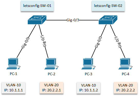
In our 2nd lab, we will go with 2 switches where same group’s workstation will be on both switches.
First of all, let’s configure on Cisco Switch 01 (letsconfig-SW-01). VLAN will be configured and then interfaces will be assigned according diagram.
letsconfig-SW-01#conf t
letsconfig-SW-01(config-vlan)#name vlan-10

letsconfig-SW-01(config)#vlan 20
letsconfig-SW-01(config-vlan)#name vlan-20
letsconfig-SW-01#conf t
letsconfig-SW-01(config)#int gigabitEthernet 0/0
letsconfig-SW-01(config-if)#switchport mode access
letsconfig-SW-01(config-if)#switchport access vlan 10

letsconfig-SW-01(config)#int gig0/1
letsconfig-SW-01(config-if)#switchport mode access
letsconfig-SW-01(config-if)#switchport access vlan 20
letsconfig-SW-01(config-if)#^Z
letsconfig-SW-01#
Our vlan database output are below –
letsconfig-SW-01#show vlan

VLAN Name                             Status    Ports
---- -------------------------------- --------- -------------------------------
1    default                          active    Gi0/2, Gi0/3, Gi1/0, Gi1/1
                                                Gi1/2, Gi1/3, Gi2/0, Gi2/1
                                                Gi2/2, Gi2/3, Gi3/0, Gi3/1
                                                Gi3/2, Gi3/3
10   vlan-10                          active    Gi0/0
20   vlan-20                          active    Gi0/1
1002 fddi-default                     act/unsup
1003 token-ring-default               act/unsup
1004 fddinet-default                  act/unsup
1005 trnet-default                    act/unsup
Similarly, we will configure our 2nd switch (letsconfig-SW-02) and verify the output.
letsconfig-SW-02#conf t
letsconfig-SW-02(config)#vlan 10
letsconfig-SW-02(config-vlan)#name vlan-10

letsconfig-SW-02(config)#vlan 20
letsconfig-SW-02(config-vlan)#name vlan-20
letsconfig-SW-02(config)#int gig0/0
letsconfig-SW-02(config-if)#switchport mode access
letsconfig-SW-02(config-if)#switchport access vlan 10

letsconfig-SW-02(config)#int gig0/1
letsconfig-SW-02(config-if)#switchport mode access
letsconfig-SW-02(config-if)#switchport access vlan 20
letsconfig-SW-01(config-if)#^Z
letsconfig-SW-01#
letsconfig-SW-02#show vlan

VLAN Name                             Status    Ports
---- -------------------------------- --------- -------------------------------
1    default                          active    Gi0/2, Gi0/3, Gi1/0, Gi1/1
                                                Gi1/2, Gi1/3, Gi2/0, Gi2/1
                                                Gi2/2, Gi2/3, Gi3/0, Gi3/1
                                                Gi3/2, Gi3/3
10   vlan-10                          active    Gi0/0
20   vlan-20                          active    Gi0/1
1002 fddi-default                     act/unsup
1003 token-ring-default               act/unsup
1004 fddinet-default                  act/unsup
1005 trnet-default                    act/unsup
Still now, we have assigned a single VLAN on an interface and seems like everything is OK. But in this example, we need to configure multiple VLANs (VLAN-10 and VLAN-20) in gig-0/3 interface on both switches. It’s because we need to exchange VLAN database between switches to allow VLAN users to communicate each other. We will do this by trunk mode.
So, let’s configure trunk –
letsconfig-SW-01#conf t
letsconfig-SW-01(config)#int gig0/3
letsconfig-SW-01(config-if)#switchport mode trunk
When we put switchport mode as trunk, we will get a rejection message if we have trunk encapsulation mode as auto. You can verify it “show interfaces switchport” command.
Command rejected: An interface whose trunk encapsulation is "Auto" can not be configured to "trunk" mode.
Therefore, you need to put below command to allow trunk. Here note that, isl (Inter Switch Link) is a Cisco proprietary protocol but it’s old. Currently everyone is using dot1q (IEEE 802.1Q). Dot1Q has less overhead and support more vlan(s). ISL didn’t support native vlan also.
letsconfig-SW-01(config-if)#switchport trunk encapsulation ?
  dot1q      Interface uses only 802.1q trunking encapsulation when trunking
  isl        Interface uses only ISL trunking encapsulation when trunking
  negotiate  Device will negotiate trunking encapsulation with peer on
             interface

letsconfig-SW-01(config-if)#switchport trunk encapsulation dot1q
So, our configuration for gig-0/3 –
letsconfig-SW-01#conf t
letsconfig-SW-01(config)#int gig0/3
letsconfig-SW-01(config-if)#switchport mode trunk
letsconfig-SW-01(config-if)#switchport trunk encapsulation dot1q
letsconfig-SW-01(config-if)#switchport trunk allowed vlan 10,20
letsconfig-SW-01(config-if)#end
letsconfig-SW-01#
Similarly, we will configure 2nd switch (letsconfig-SW-02).
letsconfig-SW-02#conf t
letsconfig-SW-02(config)#int gig0/3
letsconfig-SW-02(config-if)#switchport trunk encapsulation dot1q
letsconfig-SW-02(config-if)#switchport mode trunk
letsconfig-SW-02(config-if)#switchport trunk allowed vlan 10,20
letsconfig-SW-02(config-if)#^Z
letsconfig-SW-02#
We can check our final interface configure –
letsconfig-SW-01#show running-config interface gigabitEthernet 0/3
Building configuration...

Current configuration : 152 bytes
!
interface GigabitEthernet0/3
 switchport trunk allowed vlan 10,20
 switchport trunk encapsulation dot1q
 switchport mode trunk
 negotiation auto
end
We also can use “show interfaces switchport” command, which will give us much more details.
letsconfig-SW-01#show interfaces gigabitEthernet 0/3 switchport
Name: Gi0/3
Switchport: Enabled
Administrative Mode: trunk
Operational Mode: down
Administrative Trunking Encapsulation: dot1q
Negotiation of Trunking: On
Access Mode VLAN: 1 (default)
Trunking Native Mode VLAN: 1 (default)
Administrative Native VLAN tagging: enabled
Voice VLAN: none
Administrative private-vlan host-association: none
Administrative private-vlan mapping: none
Administrative private-vlan trunk native VLAN: none
Administrative private-vlan trunk Native VLAN tagging: enabled
Administrative private-vlan trunk encapsulation: dot1q
Administrative private-vlan trunk normal VLANs: none
Administrative private-vlan trunk associations: none
Administrative private-vlan trunk mappings: none
Operational private-vlan: none
Trunking VLANs Enabled: 10,20
Pruning VLANs Enabled: 2-1001
Capture Mode Disabled
Capture VLANs Allowed: ALL

Protected: false
Appliance trust: none
Finally, let’s check from PCs.
PC-1> ping 10.1.1.2
84 bytes from 10.1.1.2 icmp_seq=1 ttl=64 time=10.916 ms
84 bytes from 10.1.1.2 icmp_seq=2 ttl=64 time=9.113 ms
84 bytes from 10.1.1.2 icmp_seq=3 ttl=64 time=13.829 ms
84 bytes from 10.1.1.2 icmp_seq=4 ttl=64 time=13.474 ms
84 bytes from 10.1.1.2 icmp_seq=5 ttl=64 time=10.695 ms

PC-1> ping 20.2.2.1
host (255.255.255.0) not reachable
We clearly can see, we can reach same team members (VLAN-10) PC but, can’t on another team (VLAN-20) PCs. Similarly, the output of PC-2 which is under VLAN-20.
PC-2> ping 20.2.2.2
84 bytes from 20.2.2.2 icmp_seq=1 ttl=64 time=23.208 ms
84 bytes from 20.2.2.2 icmp_seq=2 ttl=64 time=10.893 ms
84 bytes from 20.2.2.2 icmp_seq=3 ttl=64 time=10.894 ms
84 bytes from 20.2.2.2 icmp_seq=4 ttl=64 time=11.342 ms
84 bytes from 20.2.2.2 icmp_seq=5 ttl=64 time=8.260 ms

PC-2> ping 10.1.1.1
host (255.255.255.0) not reachable
Sure enough, we have configured VLAN in our network.