Generic Routing Encapsulation (GRE) is a tunneling protocol that was developed to carry L3 traffic over an IP network. It encapsulates packets in a manner, so that it creates a private point-to-point link between 2 networks. In this lesson, we will learn how to configure a GRE on Juniper devices. So, let’s get started.
GRE Lab Diagram:
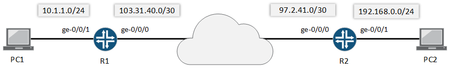
Goal:
In this Lab, we will configure GRE tunnel between R1 and R2, and then we will establish connection between network 10.1.1.0/24 with 192.168.0.0/24, which will be forwarded through GRE.
Configuration:
In GRE configuration, we have three mandatory components. These are-
- GRE P2P Tunnel IP
- Tunnel Source IP
- Tunnel Destination IP
GRE Tunnel IP is the point-to-point IP between two GRE nodes. Tunnel source is the IP gateway from a device for the GRE traffic. Usually, it’s the WAN IP and in this example, we will use WAN IP as our tunnel source. Destination IP is the IP of remote end.
Let’s verify, interfaces configuration for both R1 and R2 routers.
Interfaces configuration on R1:
rajib@R1# show interfaces
ge-0/0/0 {
    unit 0 {
        description ***WAN***;
        family inet {
            address 103.31.40.2/30;
        }
    }
}
ge-0/0/1 {
    unit 0 {
        description ***LAN***;
        family inet {
            address 10.1.1.1/24;
        }
    }
}


Interfaces configuration on R2:
rajib@R2# show interfaces
ge-0/0/0 {
    unit 0 {
        description ***WAN***;
        family inet {
            address 97.2.41.2/30;
        }
    }
}
ge-0/0/1 {
    unit 0 {
        description ***LAN***;
        family inet {
            address 192.168.0.1/24;
        }
    }
}
In our LAB, we have OSPF with ISP routers from both R1 and R2, which makes our reachability from R1 to R2. Let’s verify it using the PING command from R1 router to R2 router.
[edit]
rajib@R1# run ping 97.2.41.2
PING 97.2.41.2 (97.2.41.2): 56 data bytes
64 bytes from 97.2.41.2: icmp_seq=0 ttl=64 time=0.431 ms
64 bytes from 97.2.41.2: icmp_seq=1 ttl=64 time=0.472 ms
64 bytes from 97.2.41.2: icmp_seq=2 ttl=64 time=0.445 ms
64 bytes from 97.2.41.2: icmp_seq=3 ttl=64 time=0.517 ms
64 bytes from 97.2.41.2: icmp_seq=4 ttl=64 time=0.525 ms
^C
--- 97.2.41.2 ping statistics ---
5 packets transmitted, 5 packets received, 0% packet loss
round-trip min/avg/max/stddev = 0.431/0.478/0.525/0.038 ms
Now, we will start GRE configuration. We will use 172.16.0.0/30 for GRE point-to-point IP.
GRE on R1 Router:
set interfaces gr-0/0/0 unit 0 family inet address 172.16.0.1/30
set interfaces gr-0/0/0 unit 0 tunnel source 103.31.40.2
set interfaces gr-0/0/0 unit 0 tunnel destination 97.2.41.2
Before, committing above configuration, verify it using show | compare command. If everything OK, we will commit our new configuration.
[edit]
rajib@R1# show | compare
[edit interfaces]
+   gr-0/0/0 {
+       unit 0 {
+           tunnel {
+               source 103.31.40.2;
+               destination 97.2.41.2;
+           }
+           family inet {
+               address 172.16.0.1/30;
+           }
+       }
+   }

[edit]
rajib@R1#

[edit]
rajib@R1# commit
commit complete
Similarly, we will configure GRE for router R2. And. commit it.
GRE on R2 Router:
set interfaces gr-0/0/0 unit 0 family inet address 172.16.0.2/30
set interfaces gr-0/0/0 unit 0 tunnel source 97.2.41.2
set interfaces gr-0/0/0 unit 0 tunnel destination 103.31.40.2
Finally, we need to have a routing protocol to route 10.1.1.0/24 to 192.168.0.0/24. We can configure a static route to fulfill this.
Routing on R1 Router:
set routing-options static route 192.168.0.0/24 next-hop 172.16.0.2

Routing on R2 Router:
set routing-options static route 10.1.1.0/24 next-hop 172.16.0.1
NOTE: Don’t forget to commit new configurations.
Verification
We will ping PC2 (192.168.0.10) from PC1 (10.1.1.10) and here is the output.
root@PC1:~# ping 192.168.0.10
PING 192.168.0.10 (192.168.0.10) 56(84) bytes of data.
64 bytes from 192.168.0.10: icmp_req=1 ttl=64 time=0.213 ms
64 bytes from 192.168.0.10: icmp_req=2 ttl=64 time=0.221 ms
64 bytes from 192.168.0.10: icmp_req=3 ttl=64 time=0.209 ms
64 bytes from 192.168.0.10: icmp_req=4 ttl=64 time=0.254 ms
64 bytes from 192.168.0.10: icmp_req=5 ttl=64 time=0.558 ms
^C
--- 192.168.0.10 ping statistics ---
5 packets transmitted, 5 received, 0% packet loss, time 3999ms
rtt min/avg/max/mdev = 0.209/0.291/0.558/0.134 ms
root@PC1:~#
Below are other important commands, which will help.
run show interfaces terse | match gre
show interfaces gr-0/0/0 extensive
run show route 192.168.0.2
Let me know, if you have any questions.
Hello Rajib, is it possible that you have made a small mistake? Please take a look at the part: “.. Before, committing above configuration, verify it using show | compare command..”. Here the source and destination do not match the code above. I think in the “show | compare” Code the source should be 103.31.40.2 and the destination 97.2.41.2.
Otherwise I think your explanation is really good – thank you very much.
Hi Marcel, yes i made a mistake during the writing. Thanks for correcting me.
Hi, thank you for the explanation. if i want to use a juniper switch that sits behind a Cisco firewall, how would the config look like?
Switch configuration depends on your requirements.
hello very help full
thanks 🙂
static route in two routers is inverse.
Routing on R1 Router:
set routing-options static route 192.168.0.0/24 next-hop 172.16.0.2
Routing on R2 Router:
set routing-options static route 10.1.1.0/24 next-hop 172.16.0.1
I corrected the issue, thanks.
How do I subscribe?
You will find email subscription form in sidebar under search bar. You also can join facebook page at https://www.facebook.com/letsconfig and twitter https://www.twitter.com/letsconfig
Hi Rajib, I m falling in love with Juniper again now as i have been off it for long, i picked it up about two years and the love of it made me do the certification JNCIA and JNCIS. reading the GRE tunnel and your enthusiastic with the passion and love to help i am most impressed with the work you are doing . Thanks and hopefully i will be needing your help to learn more.
Thanks
Hi OLALEKAN, it’s my pleasure.
Hope you will subscribe for more content.
Great Nice one,
I do this every time on cisco devices and is the same you made it simple and easy to understand for others. Nice work and great.
Keep the good work
Hi Olalekan, thank you so much.