DMVPN or Dynamic Multipoint Virtual Private Network is a tunneling protocol, which helps to build scalable IPsec Virtual Private Networks (VPNs). In this lesson, we will learn to configure DMVPN on Cisco router with single HUB.
DMVPN is combine of-
- mGRE (Multipoint GRE allows a single interface to support multiple IPSec tunnel.)
- NHRP (Next Hop Resolution Protocol)
- Routing
- IPsec (not required but recommended)
DMVPN configuration:
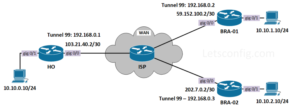
In this lab we will be using below diagram-
First of all, let’s configure IP addresses on all the routers including ISP. After that, we will configure OSPF between routers, so that WAN IPs can reach each other.
HO:
interface GigabitEthernet0/0
 description ***WAN Interface***
 ip address 103.21.40.2 255.255.255.252
 no shutdown

interface GigabitEthernet0/1
 description ***LAN Interface***
 ip address 10.10.0.1 255.255.255.0
 no shutdown
BRA-01:
interface GigabitEthernet0/0
 description ***WAN Interface***
 ip address 59.152.100.2 255.255.255.252
 no shutdown

interface GigabitEthernet0/1
 description ***LAN Interface***
 ip address 10.10.1.1 255.255.255.0
 no shutdown
BRA-02:
interface GigabitEthernet0/0
 description ***WAN Interface***
 ip address 202.7.0.2 255.255.255.252
 no shutdown

interface GigabitEthernet0/1
 description ***LAN Interface***
 ip address 10.10.2.1 255.255.255.0
 no shutdown
ISP:
interface GigabitEthernet0/0
 description ***To HO***
 ip address 103.21.40.1 255.255.255.252
 no shutdown

interface GigabitEthernet0/1
 description ***To BRA-01***
 ip address 59.152.100.1 255.255.255.252
 no shutdown

interface GigabitEthernet0/2
 description ***To BRA-02***
 ip address 202.7.0.1 255.255.255.252
 no shutdown
Now we need to configure routing between routers. Here, i am using OSPF to connect to the ISP. If you want to learn more about OSPF, you check out below contents.
++ CISCO – How to configure OSPF in Cisco Router
++ CISCO – How to Configure OSPF Authentication
++ JUNIPER – How to configure OSPF on Juniper
++ JUNIPER – How to configure Multi-Area OSPF on Juniper
HO:
router ospf 1
!
interface GigabitEthernet0/0
 ip ospf 1 area 0

BRA-01:
router ospf 1
!
interface GigabitEthernet0/0
 ip ospf 1 area 0

BRA-02:
router ospf 1
!
interface GigabitEthernet0/0
 ip ospf 1 area 0

ISP:
router ospf 1
!
interface GigabitEthernet0/0
 ip ospf 1 area 0
interface GigabitEthernet0/1
 ip ospf 1 area 0
interface GigabitEthernet0/2
 ip ospf 1 area 0
Now, lets verify the reachability from HO to BRA-01 & BRA-02.
HO#ping 59.152.100.2
Type escape sequence to abort.
Sending 5, 100-byte ICMP Echos to 59.152.100.2, timeout is 2 seconds:
!!!!!
Success rate is 100 percent (5/5), round-trip min/avg/max = 3/3/6 ms

HO#ping 202.7.0.2
Type escape sequence to abort.
Sending 5, 100-byte ICMP Echos to 202.7.0.2, timeout is 2 seconds:
!!!!!
Success rate is 100 percent (5/5), round-trip min/avg/max = 3/3/5 ms
Communication is successful. So, next configuration part will be DMVPN configuration.
mGRE and NHRP Configuration
HO (HUB):
interface Tunnel99
 description ***DMVPN Interface***
 ip address 192.168.0.1 255.255.255.0
 ip nhrp authentication LetsConf
 ip nhrp map multicast dynamic
 ip nhrp network-id 1
 tunnel source GigabitEthernet0/0
 tunnel mode gre multipoint
Explanation:
++ nhrp authentication helps to prevent unauthorized peer to join. LetsConf are key here.
++ nhrp network-id need to be same for all the sites.
++ Regular GRE tunnel has destination address, but mGRE do not have any specific destination. So, command tunnel mode gre multipoint tells that, it need to do the peer with multiple IPs.
++ nhrp map multicast dynamic help to forward multicast traffic through the tunnel.
BRA-01 & BRA-02 (SPOKE):
interface Tunnel99
 description ***DMVPN Interface***
 ip address 192.168.0.3 255.255.255.0
 ip nhrp authentication LetsConf
 ip nhrp map multicast dynamic
 ip nhrp map 192.168.0.1 103.21.40.2
 ip nhrp map multicast 103.21.40.2
 ip nhrp network-id 1
 ip nhrp nhs 192.168.0.1
 tunnel source GigabitEthernet0/0
 tunnel mode gre multipoint
Explanation:
++ ip nhrp map 192.168.0.1 103.21.40.2 command is used to statically configure the IP-to-nonbroadcast multi-access (NBMA) address mapping of IP destinations connected to an NBMA network.
++ ip nhrp nhs command specifies the address of NHRP servers.
Till now, we have configured mGRE and NHRP. In this position, we can check the status of DMVPN using show dmvpn command.
HO#show dmvpn
Legend: Attrb --> S - Static, D - Dynamic, I - Incomplete
        N - NATed, L - Local, X - No Socket
        T1 - Route Installed, T2 - Nexthop-override
        C - CTS Capable
        # Ent --> Number of NHRP entries with same NBMA peer
        NHS Status: E --> Expecting Replies, R --> Responding, W --> Waiting
        UpDn Time --> Up or Down Time for a Tunnel
===================================================

Interface: Tunnel99, IPv4 NHRP Details
Type:Hub, NHRP Peers:2,

 # Ent  Peer NBMA Addr Peer Tunnel Add State  UpDn Tm Attrb
 ----- --------------- --------------- ----- -------- -----
     1 59.152.100.2        192.168.0.2    UP 00:20:08     D
     1 202.7.0.2              192.168.0.3    UP 00:19:15     D
From the above output, we can clearly see we have GRE tunnel established with branches. Although the tunnel is up, but without routing, one site will not be able to reach another site. So, let’s add routes between them. In this example, i am going to use static routing, however you can use any dynamic routing.
HO:
ip route 10.10.1.0 255.255.255.0 192.168.0.2
ip route 10.10.2.0 255.255.255.0 192.168.0.3

BRA-01:
ip route 10.10.0.0 255.255.255.0 192.168.0.1
ip route 10.10.2.0 255.255.255.0 192.168.0.3

BRA-02:
ip route 10.10.0.0 255.255.255.0 192.168.0.1
ip route 10.10.1.0 255.255.255.0 192.168.0.2
Let’s verify the reachability from HO-PC to Branch PCs.
HO-PC> ping 10.10.1.10
84 bytes from 10.10.1.10 icmp_seq=1 ttl=62 time=5.023 ms
84 bytes from 10.10.1.10 icmp_seq=2 ttl=62 time=3.349 ms

HO-PC> ping 10.10.2.10
84 bytes from 10.10.2.10 icmp_seq=1 ttl=62 time=16.078 ms
84 bytes from 10.10.2.10 icmp_seq=2 ttl=62 time=3.679 ms
Still now, we are using basic tunneling without any encryption. Let’s add some encryption using IPSec in mGRE.
IPSec configuration for HO, BRA-01, & BRA-02
crypto isakmp policy 99
 encr 3des
 hash sha256
 authentication pre-share
 group 2
 lifetime 86400

crypto isakmp key LetsConf address 0.0.0.0 0.0.0.0

crypto ipsec transform-set TS esp-3des esp-sha256-hmac

crypto ipsec profile DMVPN-PRO
 set security-association lifetime seconds 86400
 set transform-set TS
Now, we need to apply this on the tunnel interface on HO, BRA-01, & BRA-02.
interface Tunnel99
 tunnel protection ipsec profile DMVPN-PRO
Lastly, we can verify IPSec using show crypto session command.
HO#show crypto session
Crypto session current status

Interface: Tunnel99
Session status: UP-ACTIVE
Peer: 202.7.0.2 port 500
  Session ID: 0
  IKEv1 SA: local 103.21.40.2/500 remote 202.7.0.2/500 Active
  IPSEC FLOW: permit 47 host 103.21.40.2 host 202.7.0.2
        Active SAs: 4, origin: crypto map

Interface: Tunnel99
Session status: UP-ACTIVE
Peer: 59.152.100.2 port 500
  Session ID: 0
  IKEv1 SA: local 103.21.40.2/500 remote 59.152.100.2/500 Active
  IPSEC FLOW: permit 47 host 103.21.40.2 host 59.152.100.2
        Active SAs: 4, origin: crypto map
If you interested to learn more about DMVPN, you also check this presentation on DMVPN. Hope this will be helpful.
I appreciate you, This articles really very nice and it helps to basics understanding for beginners and who want to create lab on own pc for practice.
Thanks Rakesh.
Thanks for your efforts Rajib.
You are welcome Rakesh 🙂